Everything you need to know about computer logic
This is an aspect of computer design concerning the fundamental operations and structures upon which all computer systems are built
Logic gates
Electronic pulses can be made to follow a set of rules if they are passed through certain components. These components act like electronic switches and are called gates.
The 3 common gates are the AND, OR, and NOT gates. Other such gates NOR and NAND are made by combining two of these together.

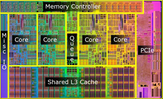
Chips
In modern computers, one or more chips are put together to form a chip. This chip contains the electronic circuitry needed for various operations.

A chip can contain all the components of a circuit that can act as a logic gate. This type of chip is called an integrated circuit. When an integrated circuit makes up all the central processing unit (CPU) except the memory. It’s called a microprocessor.
Logic elements
A gate that performs a simple operation is called a logic element. To see how these gates work we can make up a table called a truth table or operations table.
Logic diagrams
we can show logical operations in logic diagrams. In logic diagrams, we draw inputs on the left and label them with letters. Arrowed lines show the directions of the flow of logic.
The AND gate
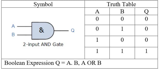
AND gates can have two or more inputs, but they only have one possible output. if the input is 1 then the output will also be 1, but in any other combinations, the output will be 0. For a two-input gate, there will be four possible combinations.
A two-input AND logic gate
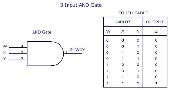
A 3-input AND logic gate
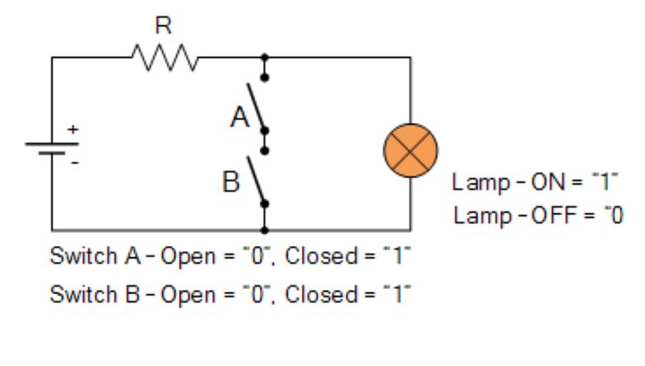
A practical application of AND gate
Gates are equivalent to combinations of switches. We can make a simple circuit using switches, a battery, and a bulb that will perform the same logical way as an AND gate.
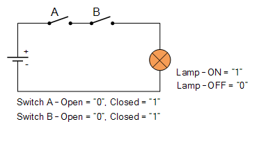
The two switches are open. Any other combination of the switches (eg A open and B closed) means the bulb will not light up.
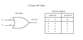
The OR gate
The Logic OR Function function states that an output action will become TRUE if either one “OR” more events are TRUE, but the order in which they occur is unimportant as it does not affect the final result.
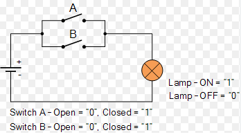
A practical application of OR gate
In an OR gate, the switches in the circuit are in parallel. in the two output circuits, the bulb will light if either switches A or B are closed. it will also light if both of the switches are closed. In the OR gates switching circuit the bulb will only write when one or more of the switches are closed.
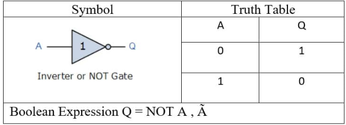
The NOT gate
Unlike the other gates, the NOT gate has only one input. But like the other gates, It has only one output. Sometimes the NOT gate is called an inverter
because it has the effect of making the output the opposite of the input, so if the input is 0 then the output is 1
Practical application of NOT gate
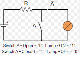
If A means that the switch is closed, then NOT A or simply à says that the switch is NOT closed or in other words, it is open. The logic NOT gate has a single input and a single output as shown
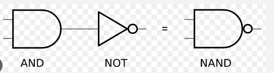
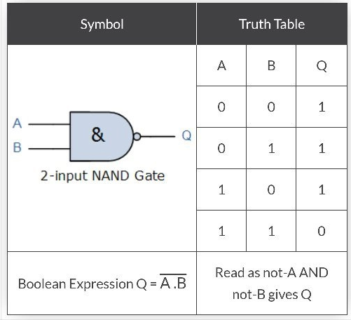
The NAND gate
The NAND gate is an AND gate followed by a NOT gate. To write its operation table we must follow the input firstly through the AND gate and then through the NOT gate
Suppose we want to find out what happens when the inputs A=0 and B=1 go through the NAND gate. First, we can work out what happens when they go through the AND gate. 0 and 1 through an and gate gives us 0. so this 0 is the input going into the NOT gate. A 0 going into a NOT gate gives an output of 1.
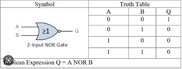
The NOR gate
The NOR gate is formed by combining an OR gate with a NOT gate. To work out the output we go through two steps. First, we work out the inputs and outputs for the OR gate. These are now the inputs for the NOT gate. The second step is working out the output of putting these inputs through the NOT gate.
**NB-**like the AND and OR gates, The NAND and NOR gates may have more than one input and like all gates, there is only ever one output.
we saw before that 0 and 1 in actual computers do not mean off and on. But it is useful to think of them as switches for explaining logic diagrams. Actually,0 means a pulse of low voltage and 1 means a pulse of high voltage.
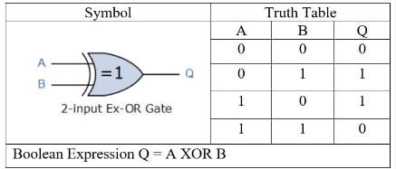
Exclusive-OR gate
An XOR gate (also known as an EOR, or EXOR gate) – pronounced as Exclusive OR gate – is a digital logic gate that gives a true (i.e. a HIGH or 1) output when the number of true inputs is odd. An XOR gate implements an exclusive OR, i.e., a true output result occurs if one – and only one – of the gate’s inputs is true. If both inputs are false (i.e. LOW or 0) or both inputs are true, the output is false.
X-NOR gate
In the XOR gate operation, the output is only 1 when only one input is 1. The output is logical 0 when both inputs are the same, meaning they are either 1 or 0. But in the XNOR gate, the inverse is true. Hence the output is 0 when only one input is 0, and the output is 1 when both inputs are the same (i.e. either two 0’s or two 1’s)